Alarm Clock using Arduino, DS1307, buzzer, and LCD
Writing this article took somewhat longer than usual, since the scope expanded on the way. Originally, I planned to only show how to use a buzzer, but then I decided to add a DS1307 real-time clock chip to it. And of course, you need a LCD display for showing the time. But unluckily, my previous LCD shield was using conflicting pins with other stuff, so I had to redo it also.
In the end, this was the result:
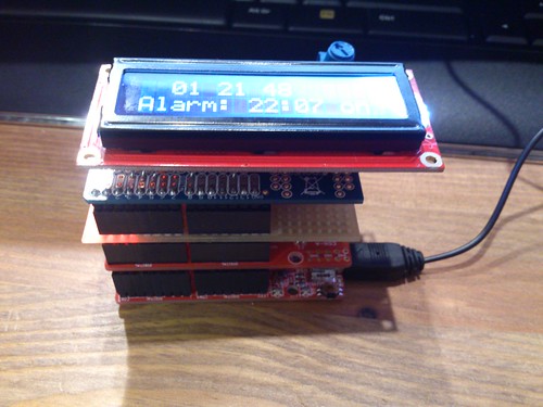
There are three shields in the picture: buzzer shield, DS1307 shield, and LCD shield. And below them is Olimexino-328, an Arduino clone. You can also use normal Arduino, but I had one Olimexino-328 at hand, so I used it.
Buzzer
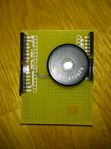
For the buzzer, I used budget proto shield from oomlout. Other end of the buzzer goes to GND and another to digital pin 9 of Arduino (pin 1 on port B in AVR documentation). When assembling the shield, I used quite big buzzer and then had to be careful what to put above it so that another shield can be put on top of the buzzer shield.
Code to make a sound via buzzer is quite simple:
procedure Play_Alarm is
   C : Unsigned_8 := 0;
begin
   MCU.DDRB_Bits (1) := DD_Output;
   MCU.PORTB_Bits (1) := False;
   loop
      for A in Unsigned_8 range 1 .. 100 loop
         MCU.PORTB_Bits (1) := True;
         delay 0.002;
         MCU.PORTB_Bits (1) := False;
         delay 0.002;
      end loop;
      delay 0.5;

      C := C + 1;
      exit when C > 5;
   end loop;
end Play_Alarm;
DS1307 Real Time Clock
To get the real time clock for the device, I combined DS1307 breakout board kit from Adafruit and Olimex proto shield. A sensible person would solder components directly on the proto shield, but since I had the breakout board ready, I simply soldered the complete board on the proto shield.
The board requires wires to 5V, GND, analog pin 4, and analog pin 5. The communication happens via I2C.

Since AVR-Ada does not have I2C or DS1307 routines by default, I used my existing I2C package and added DS1307 package, which used the I2C package.
The DS1307 package specification is here:
package DS1307 is
   subtype Year_Number     is Interfaces.Unsigned_8; -- offset to the year 2000
   subtype Month_Number    is Interfaces.Unsigned_8 range 1 .. 12;
   subtype Day_Number      is Interfaces.Unsigned_8 range 1 .. 31;
   subtype Hour_Number     is Interfaces.Unsigned_8 range 0 .. 23;
   subtype Minute_Number   is Interfaces.Unsigned_8 range 0 .. 59;
   subtype Second_Number   is Interfaces.Unsigned_8 range 0 .. 59;

   type Date_Time is record
      Seconds : Second_Number;
      Minutes : Minute_Number;
      Hours   : Hour_Number;
      Day     : Day_Number;
      Month   : Month_Number;
      Year    : Year_Number;
   end record;

   procedure Init;
   function Is_Running return Boolean;
   procedure Set_Time (New_Time : Date_Time);
   procedure Read_Time (Current_Time : out Date_Time; Status : out Boolean);
end DS1307;
First, you need to call Init. After that you can check is the clock already running by calling Is_Running function. If the clock isn't running, calling Set_Time will start it.
Finally, you can check the current time using Read_Time procedure. Status attribute will tell you was the time reading successful.
LCD Shield
I had one LCD shield done previously, but its pin configuration conflicted with pins used by Olimexino-328 and other shields, so I had to create a new LCD shield.
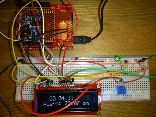
For LCD, I used a basic 16x2 display from Sparkfun. This protoshield is from And-Tech.pl/Anduino, but you can use pretty much any protoshield want. No need to try match my protoshields.
Before soldering, I tested the connections on breadboard:
And after that I made the shield:

The LCD display itself goes to the female header. The pin layout is following:
| LCD PIN | PROTOSHIELD PIN |
|---|---|
| 1 | GND |
| 2 | 5V |
| 3 | 10K TRIMPOT |
| 4 | DIGITAL 3 |
| 5 | GND |
| 6 | DIGITAL 4 |
| 7 | NONE |
| 8 | NONE |
| 9 | NONE |
| 10 | NONE |
| 11 | DIGITAL 8 |
| 12 | DIGITAL 5 |
| 13 | ANALOG 3 |
| 14 | DIGITAL 12 |
| 15 | 5V |
| 16 | GND |
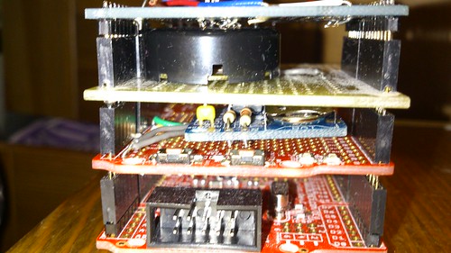
Putting things together
After I had all the shields assembled, I put them on top of each other like this:
Code
Code which I use for the alarm clock is relatively simple. In also, I cheated a little in some places. For example, while I have three unused buttons on the device (one on Olimexino-328 and two on Olimex protoshield), I am setting the time and the alarm via UART.
The initialization goes like this:
DS1307.Init;
LCD.Init;
LCD.Clear_Screen;
LCD.Put ("Initializing");
UART.Init_Interrupt_Read (UART.Baud_9600_16MHz, False, I_Ptr);
Wait_Input (Ask_Time);
if Ask_Time then
   ... -- Read time from UART
end if;

Load_Alarm (Alarm_HH, Alarm_MM, Alarm_On);

if DS1307.Is_Running then
   UART.Put("Clock is running"); UART.CRLF;
else
   UART.Put("Clock NOT running"); UART.CRLF;
end if;

LCD.Clear_Screen;
DS1307.Read_Time (Current_Time, Read_Ok);
if Read_Ok then
   Print_Time (Current_Time);
   Print_Time_LCD (Current_Time, Alarm_HH, Alarm_MM, Alarm_On);
else
   AVR.UART.Put ("DS1307: Read_Time error");
   AVR.UART.CRLF;
end if;
Above we initialize the LCD and UART. Then we wait if user wants to setup the current time. After that we load the current alarm time from EEPROM and put everything on LCD the first time.
Then we enter into the main loop.
loop
   delay 0.3;
   DS1307.Read_Time (Current_Time, Read_Ok);
   if Read_Ok then
      Print_Time (Current_Time);
      Print_Time_LCD (Current_Time, Alarm_HH, Alarm_MM, Alarm_On);
   end if;

   if UART.Have_Input then
      ... -- Handle input
   end if;

   if Current_Time.Hours = Alarm_HH and
      Current_Time.Minutes = Alarm_MM and
      not Alarm_Done then

      Alarm_Done := True;
      AVR.UART.Put ("ALARM");
      AVR.UART.CRLF;
      Play_Alarm;
   elsif (Current_Time.Hours /= Alarm_HH
       or Current_Time.Minutes /= Alarm_MM) and Alarm_Done then
      Alarm_Done := False;
   end if;

end loop;
In the loop, read time from DS1307, update time on LCD, check if user wants to change the alarm time, and play the alarm if the alarm time has been reached.
Reading DS1307 all the time is not necessary. We could also read the time to memory once a day and increase the time in memory by using AVR interrupts. There is even AVR.Real_Time package which can help us.
However, this and the button usage is left as an exercise for the reader. ;)
As usual, the code is available at arduino-alarm-clock repository.
Note: While the code is written using Ada and the required logic is quite simple, I do not guarantee that the alarm clock works 100% reliably or with a good accuracy. You should not rely on it as your only alarm clock.