Read, write, and emulate NFC tags using Adafruit PN532 breakout board, Olimexino-328, and AVR-Ada
Recently, I have been playing with PN532 breakout board from Adafruit to read NFC tags and to communicate with NFC-enabled devices, like smart phones.
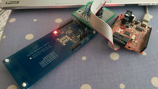
Adafruit's PN532 breakout board uses 3.3V voltage level and it is little tricky to use it with normal Arduino. So I ended up using Olimexino-328, which allows you to switch between 3.3V and 5V operation.
Setup
Olimexino-328 has special UEXT connector, so I created a small adapter board to connect PN532 breakout board to any board with UEXT, including Olimexino-328.

PN532 supports different communication options like I2C, SPI and UART. I am using SPI, since it is relatively easy to setup and if needed, software SPI is also easy to do.
NFC tags
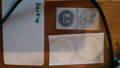
NFC tags come in various forms and types

For now, I have written code for NFC Forum type 2 and NFC Forum type 4 tags. It would be also relatively easy to support proprietary NXP Mifare Classic tags, but I haven't had time to add code for them yet.
If you are interested about the communication protocol details for various tag types, they are documented in wiki:
- NFC Forum Type 2 tags (BROKEN LINK)
- NFC Forum Type 4 tags (BROKEN LINK)
Code
The specification for my PN532 package is
package PN532 is
   type PN532_Buf is array
     (Interfaces.Unsigned_8 range <>) of Interfaces.Unsigned_8;

   subtype PN532_Buf_4 is PN532_Buf (1..4);

   subtype NFC_Forum_Type_2_Block is Interfaces.Unsigned_8 range 0 .. 63;

   CAPABILITY_CONTAINER_FILE : constant := 16#E103#;

   procedure Init;

   function PN532_SAM_Config return Boolean;
   function PN532_Read_Firmware return Interfaces.Unsigned_32;
   procedure PN532_Detect_Tag
     (Sens_Res : out Interfaces.Unsigned_16;
      Sel_Res  : out Interfaces.Unsigned_8;
      Status   : out Boolean);

   procedure PN532_Read_NFC_Forum_Type_2_Tag_Block
     (Block      : NFC_Forum_Type_2_Block;
      Buf        : out PN532_Buf;
      Byte_Count : out Interfaces.Unsigned_8;
      Status     : out Boolean);

   procedure PN532_Write_NFC_Forum_Type_2_Tag_Block
     (Block_Number : NFC_Forum_Type_2_Block;
      Buf          : PN532_Buf_4;
      Status       : out Boolean);

   function PN532_NFC_Forum_Type_4_Select_Application return Boolean;

   function PN532_NFC_Forum_Type_4_Select_File
     (File_ID : Interfaces.Unsigned_16) return Boolean;

   procedure PN532_NFC_Forum_Type_4_Read_Binary
     (Offset     : Interfaces.Unsigned_16;
      Buf        : out PN532_Buf;
      Byte_Count : out Interfaces.Unsigned_8;
      Status     : out Boolean);

   procedure PN532_NFC_Forum_Type_4_Emulate (NDEF_Message : PN532_Buf;
                                             Status : out Boolean);

   procedure PN532_NFC_Forum_Type_4_Update_Binary
     (Offset : Interfaces.Unsigned_16;
      Buf    : PN532_Buf;
      Status : out Boolean);
end PN532;
To test the code, I wrote a little application, which allows you to read a tag, write plain text content to a tag, and emulate NFC Forum type 4 tag.
---- Select action ----
1 - Read NFC tag
2 - Write NFC tag
3 - Emulate NFC Forum type 4 tag
The tag type is detected automatically, so you don't need to separately specify are you writing type 2 or type 4 tag. Also, unknown tag types are rejected so you cannot accidentally write to them.
The emulation emulates NFC Forum type 4 tag until the emulated tag is read once. For example, you can use another PN532 breakout board or Android phone to read the emulated tag contents. On Android, NFCTools is one free program which can read NFC tags.
Notes
At the moment, the PN532 code is still under work. As my time permits, I plan to add NXP Mifare tag support and also deal with PN532 error codes properly.
Formatting of NFC tags is specific to each tag model and there is no standard for it, so there is no formatting support. NFC Forum Type 2 tags do not usually require formatting, but NFC Forum Type 4 tags do. If you need to format your tags, you can do it with your smart phone.
Another thing missing is proper NDEF format support. Adafruit has some documentation, if you are interested about the issue.
The code is available under ISC license at Sourcehut.
Example hex file can be fetched from arduino-blog repository. It is compiled for 16MHz Arduino with pin configuration:
- MISO = PB4 (digital pin 12)
- MOSI = PB3 (digital pin 11)
- SS = PD7 (digital pin 7)
- Clock = PB5 (digital pin 13)