Recovering IBM Thinkpad T42 BIOS password with AVR-Ada and Arduino
My father had forgotten the BIOS password of his IBM Thinkpad T42 laptop and I promised to take a look at it.
It turns out that there is a relatively easy way to recover the password.
However, I didn't have parts described in the instructions, so instead I used Arduino and AVR-Ada.
Soldering
The BIOS password is stored on the EEPROM chip, which uses I2C for communication. To interface with the EEPROM chip, one needs to solder wires to the SDA, SCL, and GND pins of the chip and place other ends on the breadboard. The chip is powered by Thinkpad itself, so VCC pin can be left unconnected. In pictures below, I soldered the VCC pin also (but left unconnected) just in case I would have needed to provide external power to the chip.
Pin layout of the EEPROM chip (24RF08) can be found from hey-tech0.tripod.com. Atmel used to provide AT24RF08 datasheet, but now they only offer AT24C02 datasheet, which uses the same pin layout.
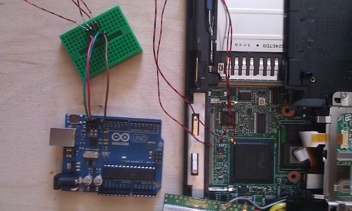

From the breadboard, connect the wires to the SDA, SCL, and GND pins of Arduino UNO r3. If you use some other Arduino, the pin locations might differ from the picture.
Reading EEPROM with AVR-Ada
To read EEPROM using Arduino and AVR-Ada, I created following program:
...
EEPROM_Address : constant := 16#40#;
...

for B in Interfaces.Unsigned_8 range 0 .. 30 loop

   Two_Wire.Init;
   Two_Wire.Request_Data(EEPROM_Address + B, 1024);
   UART.Put("Request data done: ");
   AVR.Int_Img.U8_Img (Data => EEPROM_Address + B,
      Target => I,
      Last   => L);
   AVR.UART.Put (I (1 .. L));
   UART.CRLF;
   loop
      exit when not Two_Wire.Data_Available;
      Buffer (1) := Two_Wire.Receive;
      AVR.Int_Img.U8_Img (Data => Buffer (1),
                          Target => I,
                          Last   => L);
      AVR.UART.Put("Got: ");
      AVR.UART.Put(I (1 ..L));
      AVR.UART.CRLF;
   end loop;
   Err := Two_Wire.Get_Error;
   AVR.Int_Img.U8_Img (Data => Unsigned_8 (Two_Wire.TWI_Error_Enum'Pos (Err)),
                       Target => I,
                       Last   => L);
   AVR.UART.Put("Err: ");
   AVR.UART.Put(I (1 ..L));
   AVR.UART.CRLF;
   delay 0.1;
end loop;
You can find it from my arduino-thinkpad-bios repository. The source code expects AVR-Ada 1.2 (the development version at the time of writing).
I didn't know the exact I2C address of the EEPROM, so I iterated through multiple addresses and printed out all the info I was able to get.
Note: The actual reading process happens by turning the laptop on when the wires are NOT connected to Arduino. Once the laptop is turned on and the BIOS password query appears, connect the wires and turn on or reset Arduino and read the data sent by Arduino (via serial console).
Interpreting EEPROM data
My AVR-Ada program outputs each byte (of EEPROM contents), in numeric form on its own line:
Got: 33
Got: 59
...
If you want to convert this to binary image form, you can save the output to a file and feed the file to my write_blocks.pl Perl script.
The bytes are IBM keyboard scancodes. If you have ever done any DOS games you can probably decode the bytes to characters in your head :). Otherwise, you need a program, like IBMpass v2.0 Lite (for Windows) to do the conversion.
Disclaimer
I do not guarantee that these instructions or my program is correct. It is possible that you will totally brick your laptop when you do the soldering or when you run the program on Arduino.