Controlling 4-digit 7-segment display
Introduction
A seven-segment display is nice for showing a single number. And 4-digit display is 4 times as nice since it can show four numbers.
However, using 4-digit version is also somewhat more complicated. The 4-digit 7-segment display (which I use) is done so that each digit will have same set of leds turned on at the same time when the digits are turned on. This means that if we want to show a different number in a different digit, we need to turn other digits off. Fortunately for us, other leds won't turn off immediately, so if you do turning on and off quick enough, you can set the display so that each digit shows a different number.
Setup
Required parts:
- 4-digit 7-segment display from Sparkfun
- Arduino Mega 2560 (Arduino UNO is also ok, but these instructions are tested with Mega 2560)
- Lots of jumper wires
- Four 330 or 220 ohm resistors
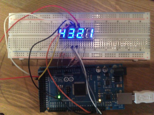
The circuit for the display is otherwise simple, but you need to be careful with the wires (since there are so many of them). If you cannot decipher the picture, there are many instructions around to follow.
The wiring table of my setup is following:
| Arduino Pin | AVR Port | Display pin | LED segment |
|---|---|---|---|
| Digital 52 | B1 | pin 11 | F |
| Digital 51 | B2 | pin 13 | C |
| Digital 50 | B3 | pin 16 | B |
| Digital 13 | B7 | pin 5 | E |
| Digital 12 | B6 | pin 3 | D |
| Digital 11 | B5 | pin 14 | A |
| Digital 10 | B4 | pin 15 | G |
| Analog 5 | F5 | pin 8 | DIG 4 |
| Analog 6 | F6 | pin 6 | DIG 3 |
| Analog 7 | F7 | pin 2 | DIG 2 |
| Analog 8 | K0 | pin 1 | DIG 1 |
You should put the resistors between the analog pins and the display.
Code
Once the circuit is done, we are ready to put the code on the device.
The code is following:
type Digit_Led is (D1, D2, D3, D4);

procedure Enable_Led (L : Digit_Led) is
begin
   case L is
      when D1 =>
         MCU.PORTF_Bits (5) := False;
         MCU.PORTF_Bits (6) := False;
         MCU.PORTF_Bits (7) := False;
         MCU.PORTK_Bits (0) := True;
      when D2 =>
         MCU.PORTF_Bits (5) := False;
         MCU.PORTF_Bits (6) := False;
         MCU.PORTF_Bits (7) := True;
         MCU.PORTK_Bits (0) := False;
      when D3 =>
         MCU.PORTF_Bits (5) := False;
         MCU.PORTF_Bits (6) := True;
         MCU.PORTF_Bits (7) := False;
         MCU.PORTK_Bits (0) := False;
      when D4 =>
         MCU.PORTF_Bits (5) := True;
         MCU.PORTF_Bits (6) := False;
         MCU.PORTF_Bits (7) := False;
         MCU.PORTK_Bits (0) := False;
   end case;
end Enable_Led;

type Digit_Type is new Unsigned_8 range 0 .. 9;
type Digit_Array is array (Digit_Type) of Unsigned_8;

Segment_Digits : Digit_Array :=
        -- EDAGBCFx
   (0 => 2#00010000#,
    1 => 2#11110010#,
    2 => 2#00000110#,
    3 => 2#10000010#,
    4 => 2#11100000#,
    5 => 2#10001000#,
    6 => 2#00001000#,
    7 => 2#11010010#,
    8 => 2#00000000#,
    9 => 2#11000000#);

procedure Show_Digit (D : Digit_Type) is
begin
   MCU.PORTB := Segment_Digits (D);
end Show_Digit;

...

loop
   Enable_Led (D4);
   Show_Digit (1);
   Wait_Some_USecs;
   MCU.PORTB := 0;

   Enable_Led (D3);
   Show_Digit (2);
   Wait_Some_USecs;
   MCU.PORTB := 0;
   ...
end loop;
The rest of the code is available from arduino-mega2560-4d-7segment repository.
And now the explanation of the code:
Enable_Led procedure turns on the specified set of leds (either for digit 1, 2, 3 or 4) and turns off other sets. Array Segment_Digits is a mapping of numbers 0..9 to the digit segments A..G so that correct leds are disabled or enable for the numbers. Procedure Show_Digit then uses this array to turn on or off the leds. Notice also how all the segment wires go to port B to make this mapping possible.
Finally, in the loop we continuously turn on and off the leds to make them look like they were always on.
The example code uses only same static set of digits. Doing a counter or timer with digits changing all the time is left as an exercise for the reader.