Running a Motor with Motorshield and Pulse Width Modulation (PWM)
Required parts:
- Arduino UNO or Duemilanove
- SeeedStudio Motor Shield
- A motor - like this
Optional parts:
- Crimp connector housing (Pololu product 1901)
- Male Crimp Pins (Pololu product 1931)
- Soldering equipment
Setup
Using a motor from Arduino is somewhat complex since you cannot directly connect the motor to the pins Arduino. Instead, for motor control you need to either build required circuit by yourself or use a motor shield.
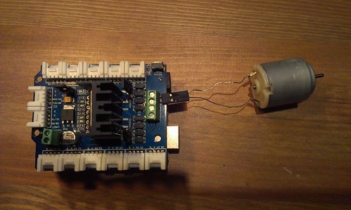
Personally, I used Seeedstudio's motor shield. In addition, I soldered crimp connectors to the wires of the motor so it is easier to plug into the shield or to a breadboard.
Once you have the motor shield and the motor, connecting them is easy, as shown in the picture above. The Seeedstudio motor shield can control two motors, I connected my motor into M1 (motor 1) pins.
Code
To run motor at various speeds, you need to use Pulse Width Modulation (PWM) feature of Arduino. While AVR-Ada provides some support for PWM, I found it easier to do my own configuration.
The M1 pins on the Seeedstudio motor shield are controlled by digital pins 8, 9, and 11 of Arduino. The digital pins 8 and 11 control the direction and pin 9 controls the speed using PWM. Wiki page has a table and description for the control logic.
The pins 8 and 11 can be programmed simply with True or False values, but pin 9 needs to be adjusted via Timer 1 since we want to use PWM. The timer 1 control is handled by writing some values to TCCR1A and TCCR1B registers (the atmega328p datasheet tells the details).
We want 8-bit fast PWM with no prescaling and it happens by setting WGM13 and WGM10 bits to False, WGM11 and WGM12 bits to True, CS11 and CS12 bits to False and CS10 bit to True. Also, COM1A1 is set to True and COM1A0 to False to clear OC1A register on the compare match:
TCCR1A_Bits := (COM1A1_Bit => True,
                COM1A0_Bit => False,
                WGM10_Bit  => True,
                WGM11_Bit  => False,
                others => False);
TCCR1B_Bits := (WGM12_Bit => True,
                WGM13_Bit => False,
                CS10_Bit => True,
                CS11_Bit => False,
                CS12_Bit => False,
                others => False);
After this we can write the speed value to OCR1A register:
MCU.OCR1A := 16#D2#;
The complete code is here:
with AVR;
with AVR.MCU;
with AVR.Timer1;

use AVR;

procedure Motor is
   use AVR.MCU;

   IN_1 : Boolean renames MCU.PORTB_Bits (0); -- digital pin 8
   IN_2 : Boolean renames MCU.PORTB_Bits (3); -- digital pin 11
   EA_1 : Boolean renames MCU.PORTB_Bits (1); -- digital pin 9

begin
   MCU.DDRB_Bits (0) := DD_Output;
   MCU.DDRB_Bits (1) := DD_Output;
   MCU.DDRB_Bits (3) := DD_Output;

   -- Clockwise rotation
   IN_1 := False;
   IN_2 := True;

   MCU.PRR_Bits (MCU.PRTIM1_Bit) := Low;
   TCCR1A_Bits := (COM1A1_Bit => True,
                   COM1A0_Bit => False,
                   WGM10_Bit  => True,
                   WGM11_Bit  => False,
                   others => False);
   TCCR1B_Bits := (WGM12_Bit => True,
                   WGM13_Bit => False,
                   CS10_Bit => False,
                   CS11_Bit => True,
                   CS12_Bit => False,
                   others => False);

   MCU.OCR1A := 16#b2#;
   loop
      null; -- busylooping
   end loop;
end Motor;
As usual, the code can be found from Sourcehut Mercurial repository: motorshield. AVR-Ada 1.2 is required.