Temperature measurement with DS18B20 and one-wire protocol
Required parts:
- Arduino UNO or Duemilanove
- DS18B20 temperature sensor
- Some jumper wires
- About 5K ohm resistor (4.7Kohm or 4.99Kohm is ok)
I had a couple of extra DS18B20 temperature sensors lying around, so I was interested in communicating with them using Arduino.
DS18B20 uses 1-wire protocol for communication and AVR-Ada supports it (1-wire and DS18B20) out of the box. But, you need to do some tweaks before 1-wire code found from AVR-Ada is usable with Arduino:
- It is best to start by copying the contents of apps/ds1820 and avr/onewire directories into a separate directory.
- Then change one_wire-avr_wiring.ads file to model your 1-wire circuit setup.
- You also need to change Processor_Speed constant in one_wire.adb to match Arduino frequency (16MHz).
Now you can compile test_ds1820.adb and other code.
Personally, I wanted a slightly different application. I planned to have multiple Arduinos measuring the temperature and the sending the value to my PC via XBees. To identify the devices, they need unique ID each. In addition, I wanted to make the temperature measurement cycle controllable (once per minute, once per an hour, once per day, etc.).
To configure these, the Arduino (and my code) waits a few seconds for input from the user and displays a simple menu if some character is received from UART. If nothing is seen, then the device reads configuration from EEPROM and starts to measure the temperature.
The UART listening code is following:
Input_Buffer : aliased AVR.Nat8_Array := (0, 0, 0, 0);

I_Ptr : AVR.UART.Buffer_Ptr :=
   AVR.UART.Buffer_Ptr'(Input_Buffer'Unchecked_Access);
...

AVR.UART.Init_Interrupt_Read (AVR.UART.Baud_9600_16MHz, False, I_Ptr);

Start_Time := AVR.Real_Time.Clock;

loop
   exit when AVR.Real_Time.Clock - Start_Time > 10.0;
   delay 0.5;
   AVR.UART.Put (".");
   if AVR.UART.Have_Input then
      ...
   end if;
end loop;
I am initializing UART routines to use interrupts and a custom input buffers. This way I can do some other things (like print dots) and still catch all the characters from UART. The above code example also shows how to use AVR.Real_Time.Clock to figure out the current time (which starts from 0 when the device boots).
The menu code and DS18B20 reading code is quite long, so I don't show them here. Instead you can find the code from the arduino-ds18b20 repository
The basic 1-wire setup for Arduino is following:
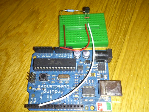
You connect the outermost pins of DS18B20 to ground and the middle pin goes to Arduino and VCC(5V) via 4.7K ohm or 5K ohm resistor.
And, since I want to use XBees, I made a shield:
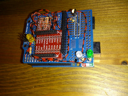
If you do not want to create your custom XBee shield, you can also use the official Wireless Shield and put DS18B20 sensor there. The shield includes a small prototyping area where the sensor should fit.